Decoding the Contactor Coil Symbol: Your Guide to Electrical Control

Ever peered at a complex electrical schematic and felt lost in a maze of lines and squiggles? Understanding the language of these diagrams is crucial for anyone working with electrical systems, and at the heart of many control circuits lies a seemingly simple, yet powerful component: the contactor. Its representation, the contactor coil symbol, is the key to unlocking a deeper understanding of how electrical power is managed.
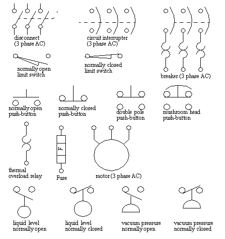
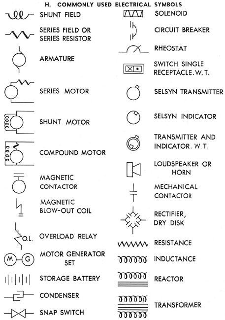
The contactor coil symbol, often a simple circle with attached terminals, acts as the brains of the contactor, a remotely controlled switch capable of handling large currents. This symbol signifies the electromagnet that, when energized, activates the contactor's contacts, allowing current to flow to a connected load. Imagine it as the trigger that sets a larger mechanism in motion. Without a clear understanding of this symbol, navigating the complexities of electrical control circuits becomes a daunting task.
The history of the contactor coil symbol is intertwined with the development of electrical control systems themselves. As the need for remotely controlling high-power circuits arose, so did the need for a standardized representation of the controlling element. The evolution of this symbol reflects the broader trend in electrical engineering towards simplified, universally recognized representations, making complex systems more accessible and understandable.
The importance of a standardized electrical symbol for the contactor coil cannot be overstated. Imagine the chaos if every manufacturer or engineer used a different symbol. The resulting ambiguity would make interpreting circuit diagrams a nightmare, increasing the risk of errors and potentially dangerous situations. The standardized symbol provides a common language, ensuring clear communication and facilitating collaboration across the electrical engineering community.
One of the main issues surrounding the contactor coil symbol, and indeed any electrical symbol, is the potential for misinterpretation. While the standardized symbol is widely recognized, variations or inaccuracies can lead to confusion. It's essential to consult reliable resources and adhere to established standards to avoid misinterpretations that can have significant consequences in the design and operation of electrical systems.
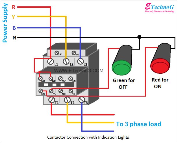
The contactor coil symbol typically appears as a circle, sometimes with a letter inside to designate its function, and two connected terminals. These terminals represent the connection points for the control voltage that energizes the coil. When voltage is applied, the coil becomes an electromagnet, pulling in a plunger that closes the contactor's contacts. A simple example: Imagine a motor control circuit. The contactor coil symbol represents the electromagnet that, when energized by a push button, closes the contactor's contacts, allowing power to flow to the motor and starting it.
Benefits of using standardized contactor coil symbols include enhanced clarity in circuit diagrams, reduced risk of misinterpretations, and simplified troubleshooting. These symbols ensure consistent communication among engineers and technicians, promoting efficient design, installation, and maintenance of electrical systems.
When working with contactor coil symbols, best practices include consulting relevant standards, using clear and concise labeling, and double-checking diagrams for accuracy. These practices minimize the risk of errors and ensure proper operation of the electrical system.
Advantages and Disadvantages of Standardized Contactor Coil Symbols
| Advantages | Disadvantages |
|---|---|
| Clear and concise representation | Potential for misinterpretation if standards are not followed |
| Universal understanding | Requires familiarity with electrical symbols |
| Simplified troubleshooting |
Frequently asked questions about contactor coil symbols often revolve around their meaning, variations, and application in different circuit diagrams. Understanding these FAQs is crucial for correctly interpreting and utilizing these symbols.
In conclusion, the seemingly simple contactor coil symbol plays a vital role in the world of electrical control. Its standardized representation ensures clear communication, facilitates efficient design and troubleshooting, and ultimately contributes to the safe and reliable operation of complex electrical systems. From controlling powerful motors to managing intricate automation processes, understanding the contactor coil symbol is essential for anyone working with electrical circuits. By adhering to established standards and best practices, engineers and technicians can harness the power of this symbol to effectively control and manage the flow of electricity in countless applications.
Unlocking radiant skin exploring light chemical peels
Goth fonts copying and pasting your way to darkness
Mastering pt cruiser torque specs your comprehensive guide


