Decoding the Language of Circuits: Schematic Symbols in Electronics

Ever wondered how engineers communicate the intricate dance of electrons within a circuit? The answer lies in a universal language: schematic symbols in electronics. These symbols, a shorthand for electronic components, are the building blocks of circuit diagrams, enabling engineers to design everything from simple LED flashlights to complex supercomputers.
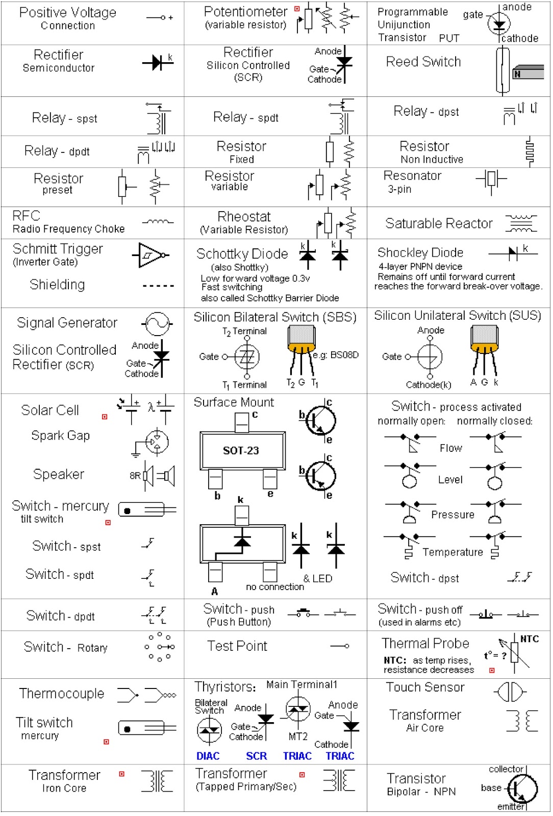
Schematic diagrams, essentially blueprints for electronic circuits, utilize these symbols to represent physical components like resistors, capacitors, transistors, and integrated circuits. Understanding these graphical representations is crucial for anyone working with electronics, from hobbyists tinkering in their garages to professionals designing cutting-edge technology.
The power of schematic symbols lies in their ability to condense complex information into a visually digestible format. Imagine trying to describe a circuit's layout using only words – it would quickly become a tangled mess of descriptions. Schematic symbols provide a clear, concise, and standardized way to depict circuit functionality.
The history of schematic symbols is intertwined with the evolution of electronics itself. As new components were invented, new symbols were created to represent them. This standardization effort has led to a globally recognized system, ensuring that engineers worldwide can understand and collaborate on circuit designs regardless of language barriers.
However, navigating the world of schematic symbols can present challenges. With a vast library of symbols, keeping up with the latest additions and variations can be daunting. Misinterpreting a symbol can lead to design errors and malfunctioning circuits. This is where proper training and access to reliable resources become paramount.
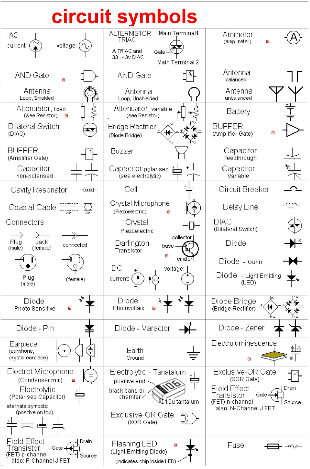
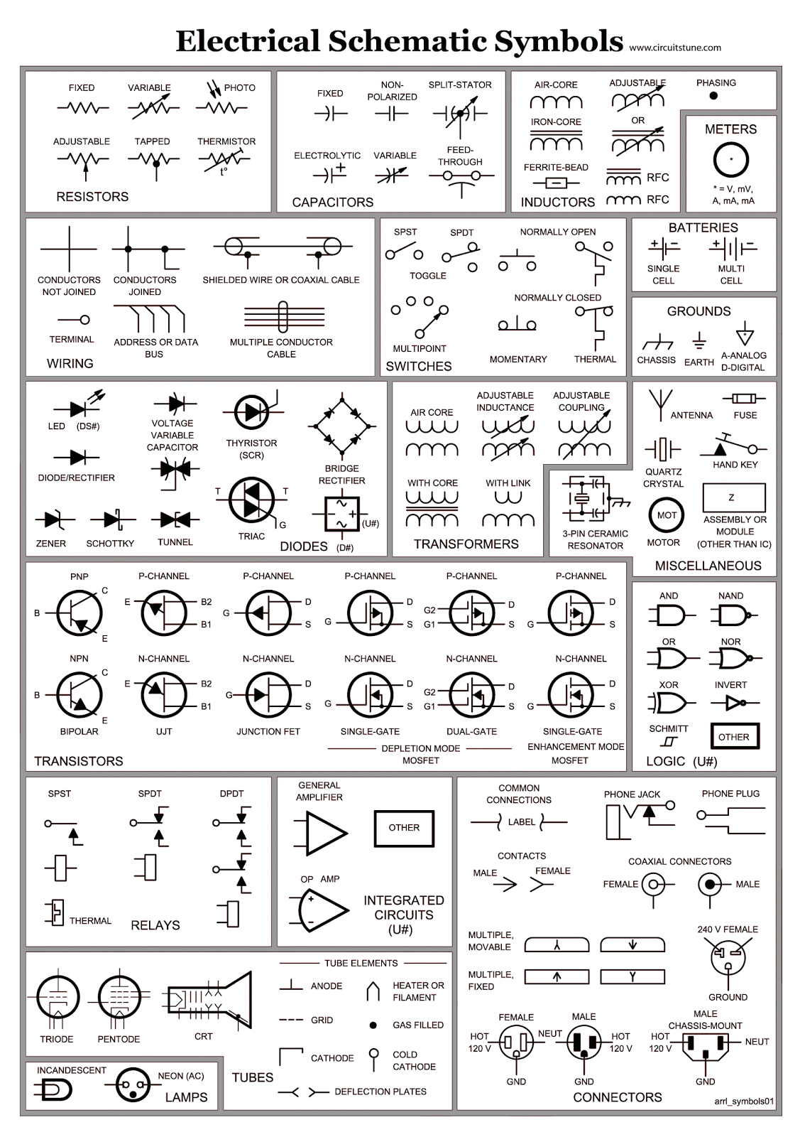
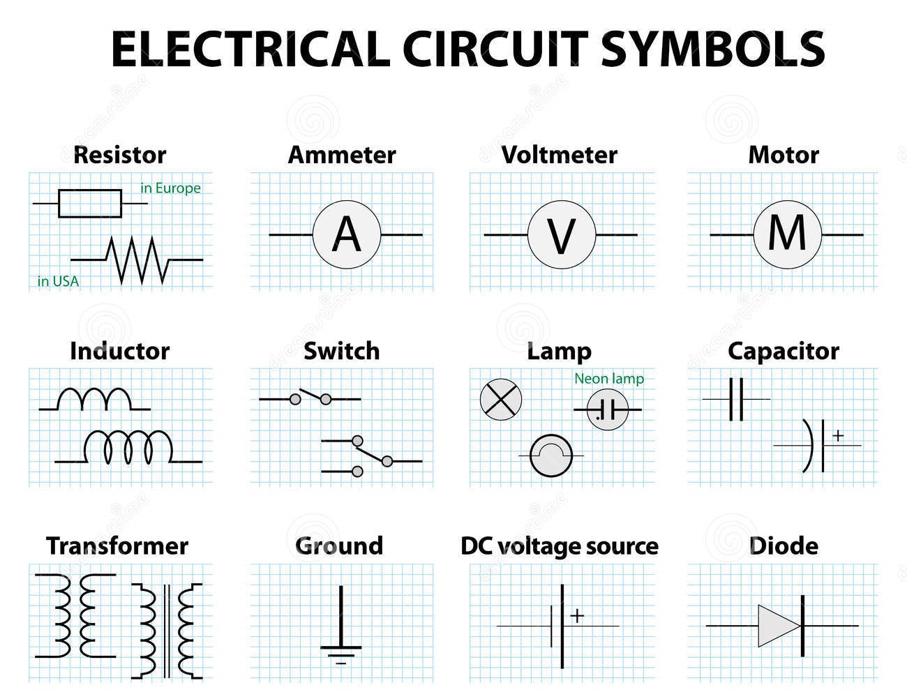
A resistor, for instance, is represented by a zig-zag line, while a capacitor is depicted by two parallel lines. A diode, which allows current to flow in only one direction, is symbolized by a triangle pointing towards a line. These simple representations encapsulate the essential function of each component.
One key benefit of using schematic symbols is improved communication and collaboration. Engineers across the globe can understand a circuit diagram regardless of their native language, fostering international collaboration and innovation.
Secondly, schematic symbols facilitate efficient circuit design. Using these standardized representations, engineers can quickly sketch and analyze circuit behavior without the need for lengthy textual descriptions.
Finally, schematic symbols are crucial for troubleshooting and repairing electronic devices. By following the symbolic representation, technicians can identify faulty components and restore functionality.
Creating a simple circuit, such as an LED light, starts by placing the battery symbol, followed by the resistor symbol connected in series to the LED symbol. The orientation of the LED symbol indicates its polarity.
Advantages and Disadvantages of Schematic Symbols
| Advantages | Disadvantages |
|---|---|
| Universal Understanding | Requires Learning |
| Simplified Design | Can be Complex for Large Circuits |
| Efficient Troubleshooting | Symbol Variations Can Cause Confusion |
Best practices for using schematic symbols include adhering to industry standards (like IEEE), using consistent symbol libraries, clearly labeling components, and ensuring diagram neatness for readability.
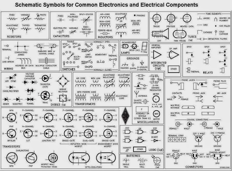
Examples of schematic symbols include the resistor, capacitor, diode, transistor, and integrated circuit. Each symbol conveys the component's function and characteristics within the circuit.
Challenges in using schematic symbols might include keeping up with new symbols and variations, interpreting complex diagrams, and ensuring consistency across different design tools. Solutions involve utilizing up-to-date resources, employing simulation software, and adhering to standardized libraries.
Frequently asked questions include: What does a ground symbol represent? How do I identify a transistor symbol? What is the significance of polarity in component symbols? How do I interpret complex integrated circuit symbols? What are the different types of logic gate symbols? How can I learn schematic symbols effectively? Where can I find reliable resources for schematic symbols? What are some common mistakes to avoid when using schematic symbols?
Tips for working with schematic symbols include using online symbol libraries, practicing drawing simple circuits, and utilizing software tools to create and simulate circuits.
In conclusion, schematic symbols in electronics are the fundamental language of circuit design. Their importance stems from their ability to simplify complex systems, facilitate communication, and empower innovation. From the earliest days of electronics to today's advanced circuitry, schematic symbols have played a vital role. By understanding and mastering this symbolic language, you unlock the power to design, analyze, and troubleshoot electronic circuits, ultimately shaping the future of technology. Explore available resources, practice reading and creating schematics, and embrace the power of visual communication in electronics. The world of electronics awaits, and the key to unlocking its potential lies in understanding the language of schematic symbols.
Unlocking the perfect palette decoding benjamin moore rgb values
Dressing to impress short curvy figures
The great thaw unpacking the end of the last ice ages continental shift

.jpg)

