Understanding Contactor Coil Symbols in Electrical Diagrams

Electrical diagrams are the language of electricians, providing a blueprint for complex electrical systems. A key component in many of these systems is the contactor, an electrically controlled switch used for switching high-current loads. Understanding the graphical representation of the contactor coil, the heart of the contactor, is essential for interpreting these diagrams accurately.
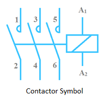
The symbol for a contactor coil is a crucial element in electrical schematics. It signifies the electromagnet that, when energized, closes the contactor's contacts, allowing current to flow to the controlled load. This seemingly simple symbol represents a powerful function within the overall circuit design, playing a role in motor control, lighting systems, and many other applications.
Representing contactor coils effectively on diagrams is fundamental for clear communication and safe operation of electrical systems. Misinterpreting the coil symbol can lead to wiring errors, malfunctioning equipment, and even safety hazards. Therefore, standardizing these symbols is vital for ensuring consistency and preventing misunderstandings among engineers, technicians, and electricians.
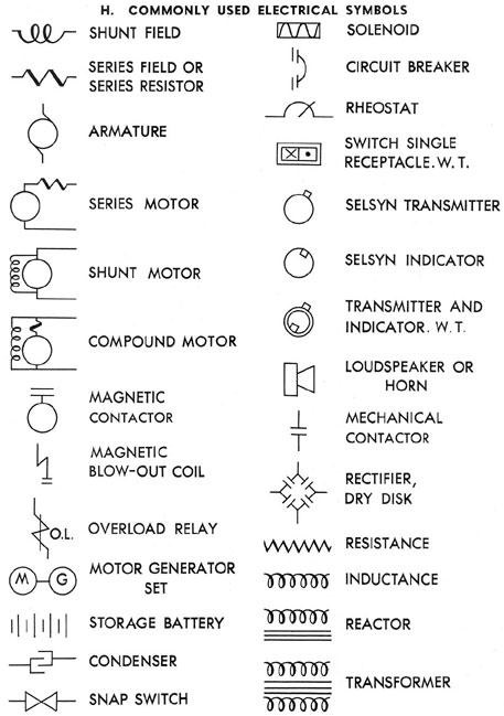
The depiction of a contactor coil can vary slightly depending on the specific standard being used, but generally, it appears as a circle with a letter designation inside. This letter typically corresponds to the coil's function or the device it controls. Accompanying the coil symbol are connection points representing the coil's terminals. This allows for clear visualization of how the coil is integrated within the broader electrical circuit.
Historically, the need for a clear and concise symbol for contactor coils emerged alongside the development of complex electrical control systems. As systems grew more intricate, the necessity for a universally understood visual language became apparent. The standardized symbol allows for efficient communication and minimizes the risk of misinterpretation, regardless of language barriers or individual experience levels.
The importance of correctly interpreting contactor coil depictions in electrical drawings cannot be overstated. It's essential for troubleshooting, maintenance, and system modifications. Understanding these symbols ensures that technicians can accurately diagnose problems, make necessary repairs, and implement changes without jeopardizing the safety and functionality of the electrical system.
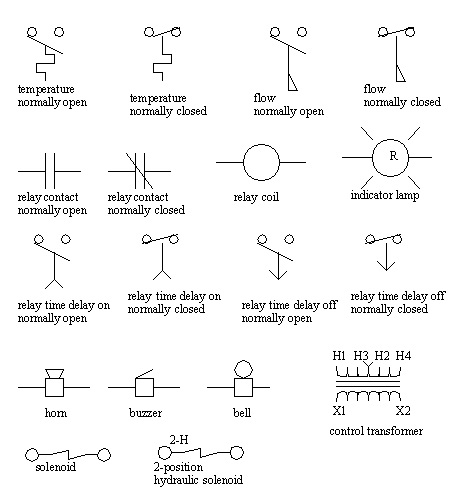
A common issue related to contactor coil symbols is variations in representation across different standards or drawing practices. While the core concept remains similar, slight differences can sometimes create confusion. Consulting relevant standards and style guides is crucial to ensure a proper understanding of the specific symbols used in a particular diagram.
A simple example of a contactor coil symbol application is in a motor starter circuit. The coil symbol, often marked with "M," represents the coil that, when energized, closes the contactor contacts, allowing power to flow to the motor. This straightforward example highlights the coil's role in controlling a significant load within a common electrical setup.
Advantages and Disadvantages of Standardized Contactor Coil Symbols
| Advantages | Disadvantages |
|---|---|
| Clear communication and understanding across different professionals | Potential variations between different standards can cause initial confusion. |
| Reduced risk of misinterpretation and wiring errors | Requires training and familiarity with the relevant standards. |
| Facilitates troubleshooting and maintenance |
Best Practices for Using Contactor Coil Symbols:
1. Adhere to established standards: Always follow relevant industry standards for symbol representation.
2. Clearly label coil designations: Ensure each coil has a clear letter designation related to its function.
3. Show connection points accurately: Depict the coil terminals correctly to clarify wiring connections.
4. Maintain consistency throughout the diagram: Use the same symbol style for all contactor coils within a single schematic.
5. Provide a legend or key if necessary: Include a legend to clarify any non-standard or ambiguous symbols.
Frequently Asked Questions:
1. What does the circle in the contactor coil symbol represent? (The coil itself)
2. Why is the letter designation important? (Identifies the controlled function)
3. Can the contactor coil symbol vary? (Slightly, depending on the standard)
4. What happens when the coil is energized? (Closes the contactor contacts)
5. Why are standardized symbols important? (Clear communication and safety)
6. How can I learn more about contactor coil symbols? (Consult electrical textbooks and standards)
7. What are the common mistakes when interpreting these symbols? (Confusing variations or neglecting designations)
8. How do I identify the coil terminals in the symbol? (Look for connection points associated with the circle)
Tips and Tricks:
When working with electrical diagrams featuring contactor coils, always double-check the symbol's designation and connection points to confirm accurate wiring. Refer to the diagram legend or relevant standards if any uncertainties arise.
In conclusion, the symbol for a contactor coil serves as a critical shorthand in electrical diagrams, conveying vital information about the control and operation of electrical systems. Understanding its representation, variations, and associated best practices is paramount for anyone working with electrical schematics. Proper interpretation of these symbols ensures accurate wiring, efficient troubleshooting, and safe operation of the systems they represent. By mastering the language of electrical diagrams, professionals contribute to a safer and more reliable electrical world. Take the time to familiarize yourself with relevant standards and best practices. This knowledge will enhance your ability to interpret electrical drawings effectively and contribute to safe and reliable electrical installations.
Dreaming of custer county your property search starts here
Double the bass powering two subs with a mono amp
The subtle art of the belated birthday wish


