Understanding Electrical Schematic Symbols

Imagine trying to build a complex electronic device without a clear blueprint. It would be a confusing and likely unsuccessful endeavor. Schematic diagrams, with their specialized symbols, serve as the blueprints of the electronics world. Understanding these symbols is essential for anyone working with circuits, from hobbyists to seasoned engineers.
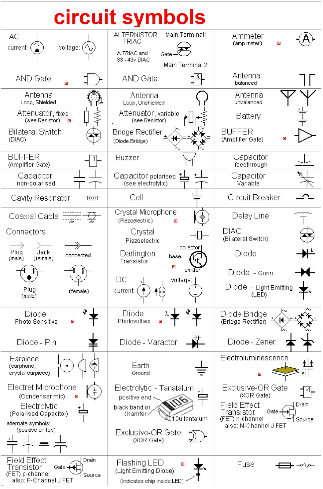
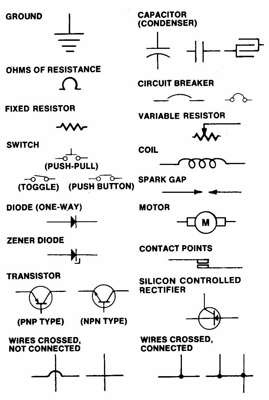
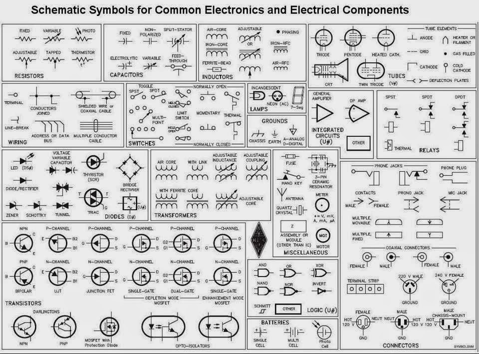
A schematic diagram symbol list, or library, is a crucial resource. It provides a standardized visual language for representing electronic components and their connections. This standardized approach ensures clear communication and minimizes errors during design, construction, and troubleshooting.
The use of symbols in diagrams has a long history, evolving alongside technological advancements. Early schematics often used simplified pictorial representations. As electronics became more complex, the need for a standardized, abstract symbol set became evident. These symbols allow engineers to represent complex circuits concisely, focusing on functionality rather than physical appearance.
The importance of a consistent schematic symbol set cannot be overstated. It facilitates collaboration, enabling engineers worldwide to understand and work on the same designs. This standardization also simplifies the learning process for newcomers to the field. Imagine the chaos if every engineer used their own unique symbols – communication would break down, and projects would become incredibly difficult to manage.
One of the main issues related to schematic diagrams is keeping up with the ever-expanding library of symbols. As new components are developed, new symbols must be created and standardized. This requires ongoing effort from organizations like the IEEE (Institute of Electrical and Electronics Engineers) to maintain consistency and clarity.
A resistor, for instance, is represented by a zig-zag line. A capacitor might be shown as two parallel lines. These simple graphical elements represent real-world components, conveying information about their function within the circuit. A complete schematic diagram symbol list encompasses a wide range of components, from basic resistors and capacitors to complex integrated circuits.
Clear communication is the primary benefit of using standardized schematic symbols. Misinterpretations can lead to costly errors and delays in project completion. Using standardized symbols ensures everyone is on the same page. Secondly, using symbols allows for concise representation. Imagine having to draw a realistic image of every component in a complex circuit! Symbols allow for compact and easy-to-understand diagrams. Finally, standardized symbols simplify troubleshooting. A technician can quickly identify and diagnose problems in a circuit by referencing the symbols in the schematic.
Effective use of a schematic diagram involves understanding the symbols and their interconnections. Start by familiarizing yourself with a comprehensive symbol list. Then, practice reading and interpreting existing schematics. Finally, begin creating your own simple diagrams to solidify your understanding. Successful implementation leads to clear, efficient communication and streamlined project development.
Advantages and Disadvantages of Standardized Schematic Symbols
| Advantages | Disadvantages |
|---|---|
| Clear Communication | Requires Learning |
| Concise Representation | Constant Updates |
| Simplified Troubleshooting | Potential for Ambiguity (if not used correctly) |
Best practices include using a consistent symbol library, labeling all components clearly, and maintaining neat and organized diagrams. Always double-check your work for errors before implementing a design. Real-world examples of schematic diagram usage can be found in virtually any electronic device, from simple toys to sophisticated computers.
Challenges related to schematic symbols might involve learning a new set of symbols or adapting to changes in standards. The solution is to commit to continuous learning and stay updated with the latest industry practices.
Common questions include: Where can I find a comprehensive symbol list? How do I interpret complex diagrams? What are the most common symbols? The answers can typically be found in engineering textbooks, online resources, and industry standards documents.
A tip for working with schematic diagrams is to organize your symbols logically and use clear labels. This improves readability and reduces the risk of errors. Another trick is to use software tools that offer built-in symbol libraries and automated diagram creation features.
In conclusion, schematic diagram symbols are the foundational language of electronics. They provide a clear, concise, and standardized way to represent complex circuits. Mastering these symbols is essential for anyone involved in the design, construction, or troubleshooting of electronic devices. By embracing standardized symbols and adhering to best practices, engineers can ensure clear communication, minimize errors, and streamline project development. The benefits of using standardized symbols extend beyond individual projects, fostering collaboration and innovation across the entire electronics industry. Continue learning and exploring the vast world of schematic symbols to deepen your understanding and enhance your abilities in this exciting field. Explore available resources like online libraries, software tools, and educational platforms to further develop your proficiency. Take advantage of the wealth of information available to master this essential skill.
Foods to avoid when you have a cough
Maximize your bowling game find the perfect ball cleaner
Navigating pennsylvania family court dockets a comprehensive guide


.jpg)