Unlocking Pneumatic Power: Your Guide to Pneumatic Symbols

Imagine a world where complex machinery dances to the tune of compressed air, silently and efficiently powering industries from manufacturing to robotics. This isn't science fiction—it's the reality of pneumatics. But to harness this power, you need a key: understanding the language of pneumatic symbols. This guide is your passport to fluency, unlocking the potential of pneumatic system design and troubleshooting.
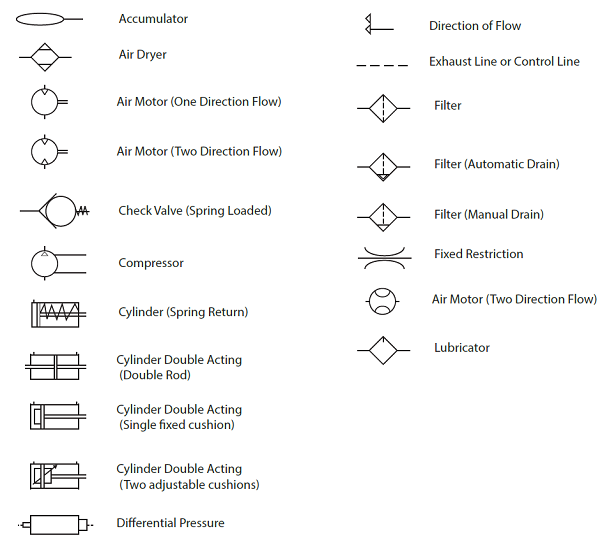
Pneumatic symbols, often compiled into handy downloadable PDFs, are the universal language of pneumatic circuits. Think of them as the musical notes on a complex score. Each symbol represents a specific component, from simple valves to intricate actuators. By learning these symbols, you're gaining the ability to read and interpret pneumatic circuit diagrams – the blueprints of any pneumatic system. This knowledge empowers you to design, build, maintain, and troubleshoot pneumatic systems effectively.
The history of pneumatic symbols is closely tied to the development of standardized engineering drawings. As pneumatic systems became more complex, a universal symbolic language became crucial for clear communication and collaboration among engineers. Organizations like ISO (International Organization for Standardization) played a key role in defining these symbols, ensuring consistency and interoperability across different industries and countries. Finding a reliable pneumatic symbols PDF, preferably one adhering to ISO standards, is an essential first step in your pneumatic journey.
Why are these symbols so important? Imagine trying to build a house without blueprints, or assemble a complex piece of furniture without instructions. It's a recipe for disaster. Similarly, trying to work with pneumatic systems without understanding the symbols is incredibly inefficient and can lead to costly errors. A well-structured pneumatic diagram, based on standardized symbols, provides a clear and concise representation of the system, allowing for efficient troubleshooting, maintenance, and modification.
One of the main challenges with pneumatic symbols is the sheer number of them. It can seem overwhelming at first. However, like learning any new language, it becomes easier with practice. Start with the basic symbols, like directional control valves, actuators, and air compressors. Gradually expand your vocabulary by exploring different types of valves, cylinders, and other components. A comprehensive "all pneumatic symbols pdf" can serve as a valuable reference during this learning process.
A typical pneumatic circuit diagram isn't just a collection of random symbols; it tells a story. It shows how compressed air flows through the system, activating different components in a specific sequence. By understanding these visual narratives, you can diagnose problems, optimize performance, and even design entirely new systems.
Benefits of having a pneumatic symbols PDF include easy access to a comprehensive symbol library, portability for on-the-go reference, and the ability to quickly share information with colleagues. You can print it, keep it on your tablet, or even access it on your smartphone, making it a powerful tool in your pneumatic toolkit.
To effectively use a pneumatic symbols PDF, familiarize yourself with the basic symbol categories (e.g., directional control valves, actuators, air preparation units). Practice reading simple circuit diagrams, then gradually move on to more complex ones. Supplement your learning with practical experience whenever possible. Building and troubleshooting real pneumatic systems will solidify your understanding of the symbols and their function.
Advantages and Disadvantages of Using Pneumatic Symbols PDF
| Advantages | Disadvantages |
|---|---|
| Portable and readily available | Static, doesn't offer interactive simulations |
| Comprehensive reference for various symbols | Can be overwhelming for beginners due to sheer volume |
| Easy to share and distribute | Requires active learning and practice for effective use |
Best Practices for Using Pneumatic Symbols:
1. Adhere to ISO standards for consistency.
2. Keep your diagrams clean and well-organized.
3. Use clear labels and annotations.
4. Regularly update your symbol library.
5. Practice reading and interpreting complex diagrams.
Frequently Asked Questions:
1. Where can I find a reliable pneumatic symbols PDF? - Search online for "ISO pneumatic symbols PDF" or consult engineering textbooks.
2. How do I interpret complex pneumatic diagrams? - Start by identifying the main components and follow the flow of air through the system.
3. What are the most common pneumatic symbols? - Directional control valves, actuators, and air preparation units are among the most frequently used.
4. Are there any software tools for creating pneumatic diagrams? - Yes, several CAD and simulation software packages offer dedicated tools for pneumatic circuit design.
5. How can I learn more about pneumatic systems? - Explore online tutorials, textbooks, and consider taking a formal course in pneumatics.
6. Why is standardization important for pneumatic symbols? - Standardized symbols ensure clear communication and prevent misinterpretations among engineers.
7. How often are pneumatic symbols updated? - ISO standards are periodically reviewed and updated to reflect advancements in pneumatic technology.
8. Are there specialized pneumatic symbols for specific industries? - While the core symbols remain consistent, some industries may use specialized symbols for specific applications.
Tips and Tricks: Create flashcards with pneumatic symbols to aid memorization. Practice sketching simple circuits by hand. Join online forums and communities to connect with other pneumatics enthusiasts.
In conclusion, mastering pneumatic symbols isn't just about memorizing a collection of shapes; it's about unlocking the potential of a powerful technology. By understanding the language of pneumatics, you gain the ability to design, build, and maintain efficient and reliable systems. Whether you're a seasoned engineer or just starting your journey in the world of pneumatics, a comprehensive "all pneumatic symbols pdf" is a valuable asset. It's your key to understanding the intricate dance of compressed air and harnessing its power for countless applications. Invest in your pneumatic literacy, and you'll open doors to a world of exciting possibilities. So, grab your pneumatic symbols PDF and start exploring the fascinating world of pneumatic power!
Bollinger champagne a james bond legacy review
Atlantas redheaded rhymesayers a look at the citys fiery emcees
Extreme engineering boat trailers mastering the art of heavy duty hauling


