Unlocking the Secrets of Triangular Wave Generators

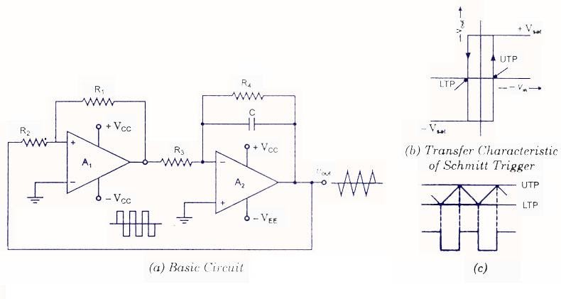
Ever wondered how those crisp, triangle-shaped waves are created in electronics? They're the product of a clever circuit known as a triangular wave generator. Understanding the triangular wave generator diagram is key to unlocking its potential in a myriad of applications.
From music synthesizers to test equipment, the triangular wave generator circuit finds its place in various technologies. This article will delve into the inner workings of these generators, exploring the triangular wave generator circuit diagram and its practical implementations. We'll cover everything from basic principles to advanced techniques, making you a pro in triangular wave generation.
So, what exactly is a triangular wave generator? It's an electronic circuit designed to produce a periodic waveform that resembles a series of connected triangles. Unlike sine waves, which have smooth curves, triangular waves have straight, rising and falling edges. This distinct characteristic makes them valuable for testing amplifiers, calibrating instruments, and even creating unique sounds in musical instruments. Analyzing the triangular waveform generator diagram allows us to understand how these waves are generated and controlled.
The foundation of a triangular wave generator often lies in an integrator circuit followed by a comparator. The integrator ramps the voltage up and down, creating the sloping sides of the triangle, while the comparator acts as a switch, reversing the direction of the ramp. The resulting output is the familiar triangular wave. Understanding the interplay of these components within the triangular wave generator schematic is crucial for designing and troubleshooting these circuits.
By mastering the triangular wave generator diagram, you gain the power to tailor the wave's characteristics to your specific needs. Adjusting the component values within the circuit allows you to control the frequency and amplitude of the generated wave, giving you precise control over the output signal. This flexibility makes triangular wave generators a versatile tool in any electronics enthusiast's arsenal.
The precise origin of the triangular wave generator is difficult to pinpoint, but its development is intertwined with the evolution of electronics and signal processing. Early function generators, devices capable of producing various waveforms, incorporated circuits similar to modern triangular wave generators. These early implementations likely relied on vacuum tubes and later transitioned to transistor-based designs as semiconductor technology advanced.
Triangular waves are important in various fields. They are used in music synthesis to create unique timbres, in function generators for testing and calibration, and in voltage-controlled oscillators (VCOs) for frequency modulation. A key issue related to triangular wave generators is maintaining linearity in the rising and falling edges. Non-linearity can introduce distortions and affect the accuracy of the generated wave.
A simple triangular wave generator can be built using an operational amplifier (op-amp) configured as an integrator and a comparator. The integrator creates the ramp, and the comparator switches the direction of the ramp. By adjusting the resistor and capacitor values, the frequency of the generated triangle wave can be controlled.
Benefits of using a triangular wave generator include: 1) Simple circuit design, making it easy to implement. 2) Precise control over frequency and amplitude. 3) Useful for various applications, such as testing and music synthesis.
An action plan for building a triangular wave generator involves selecting the appropriate op-amp, resistors, and capacitors, designing the circuit on a breadboard, and testing the output waveform using an oscilloscope.
Advantages and Disadvantages of Triangular Wave Generators
| Advantages | Disadvantages |
|---|---|
| Simple Circuitry | Limited Applications Compared to Sine Wave Generators |
| Precise Frequency Control | Potential for Non-Linearity |
| Useful for Testing and Calibration | Susceptibility to Noise |
Best practices include choosing high-quality components, using a stable power supply, and properly grounding the circuit. Real-world examples include using a triangular wave to test amplifier linearity or as a modulation source in a synthesizer.
Challenges can include noise and distortion, and solutions involve proper shielding and filtering. FAQs include questions about frequency control, amplitude adjustment, and circuit troubleshooting.
Tips and tricks include using a potentiometer for fine-tuning the frequency and using a decoupling capacitor to reduce noise. A triangular wave generator diagram visually represents the circuit's structure and components, helping in understanding and building the generator. This diagram serves as a roadmap, guiding you through the connections and functionalities of each component.
In conclusion, understanding the triangular wave generator diagram is crucial for anyone working with electronic circuits and signal generation. From its basic operating principles to its diverse applications, the triangular wave generator offers a unique set of characteristics that make it a valuable tool. By mastering its design and implementation, you can harness its power for various purposes, including testing, calibration, and even music creation. The simplicity of its design and the precision it offers in frequency control make it an essential component in the electronics world. Explore the possibilities, experiment with different configurations, and unlock the full potential of triangular wave generators. Don't hesitate to delve deeper into the resources available online and offline to further expand your knowledge and expertise in this fascinating area of electronics.
Laylas genshin impact attire a comprehensive guide
Unlocking the enigma john vaughns financial success
The art of the flirt navigating the landscape of romantic expressions


